EMKO PROJECT combines in-house mechanical and electrical design, production engineering and facilities in Ledeč nad Sázavou and Pardubice – Semtín. We use Siemens Solid Edge for mechanical 3D design, TPV2000 for production preparation and additional specialist software for the relevant discipline. Design and documentation feed directly into fabrication, assembly, installation and inspection. Facilities also include in-house wet painting and powder coating, abrasive blasting including wet blasting, and a laser centre for cutting, marking, cleaning and welding.
Mechanical design, electrical engineering and production under one technical lead.
Our design team develops the brief into models, drawings and information for production, procurement and installation. Mechanical and electrical design are coordinated across connection dimensions, instrument locations, power, signals and maintenance access.
Mechanical design · Siemens Solid Edge
Our in-house mechanical designers use Siemens Solid Edge to develop 3D part and assembly models and the associated engineering drawings. The design defines functional dimensions, materials and assembly interfaces so that the documentation supports both fabrication and equipment assembly.
3D part and assembly models
Manufacturing and assembly drawings with bills of materials
Connection dimensions and installation information
Electrical design and engineering
Our in-house electrical team develops power-supply designs, circuit diagrams, switchboard documentation and equipment interconnections to the project brief. Instruments, drives, measurement and control signals are coordinated with the mechanical design, producing information for panel assembly, installation and commissioning.
Electrical diagrams and switchboard documentation
Instrument, cable and interconnection schedules
Measurement, drive and control-system interfaces
Production preparation · TPV2000
We use TPV2000 for production preparation. Engineering information is developed into bills of materials and manufacturing routes linked to materials, individual operations and assembly. Approved changes are reflected in the information used for purchasing and production.
Bills of materials and material requirements
Manufacturing routes and operation sequences
Current information for purchasing, production and assembly
Additional specialist software supports equipment sizing, calculations and configuration for the relevant discipline and application. Its outputs form part of the coordinated project documentation, with recorded revisions and approved changes.
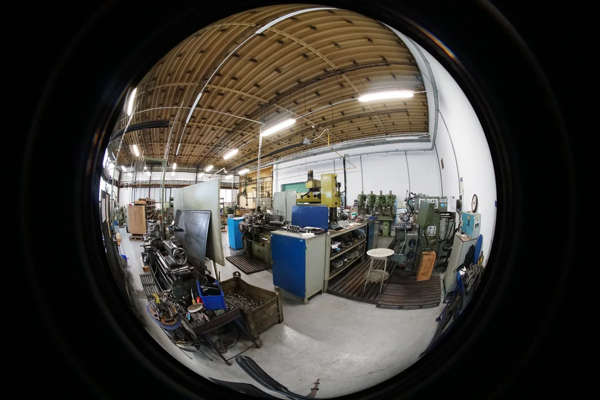
Machining workstations at the manufacturing facilities in Ledeč nad Sázavou.Archive photograph
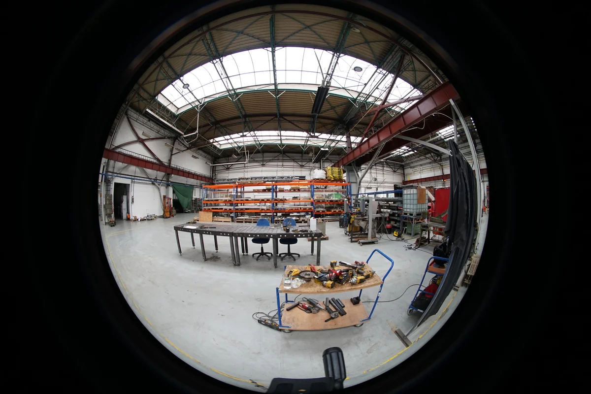
Welding and assembly workstations in Ledeč nad Sázavou.Archive photograph
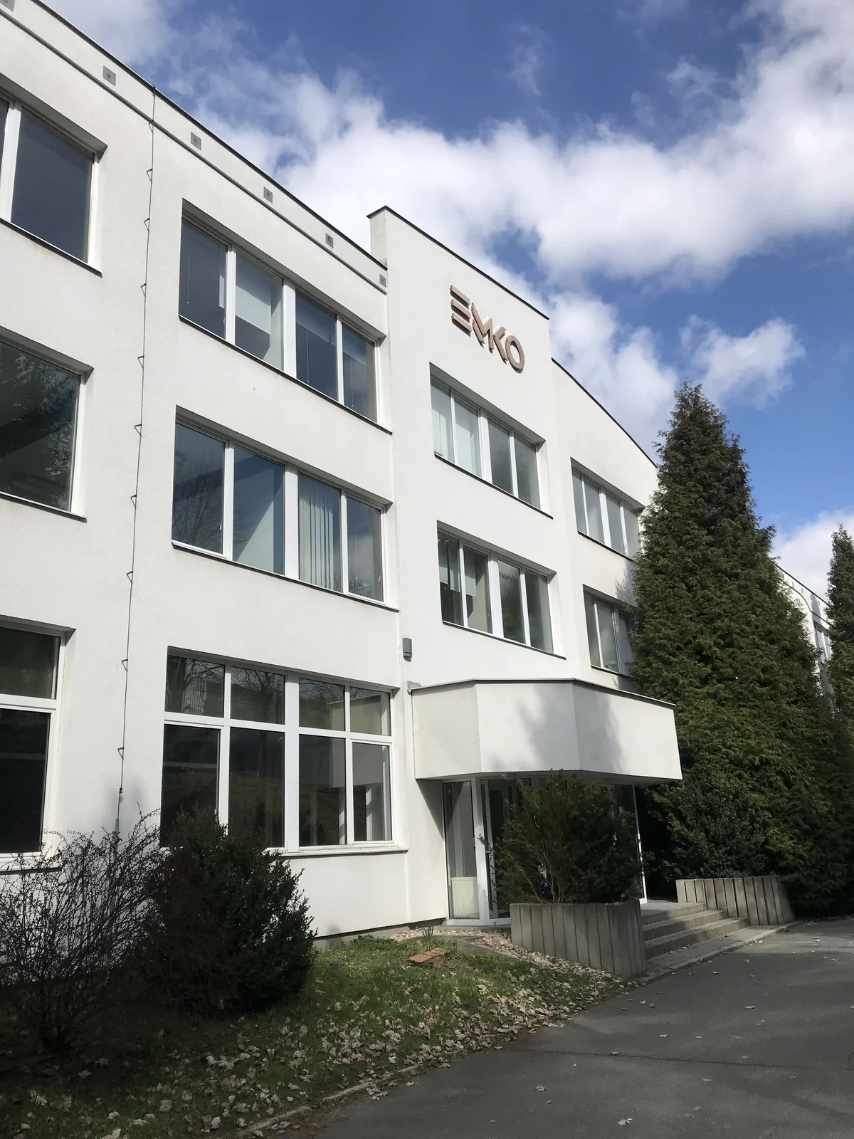
EMKO facilities in Ledeč nad Sázavou – view of the administration building.Archive photograph
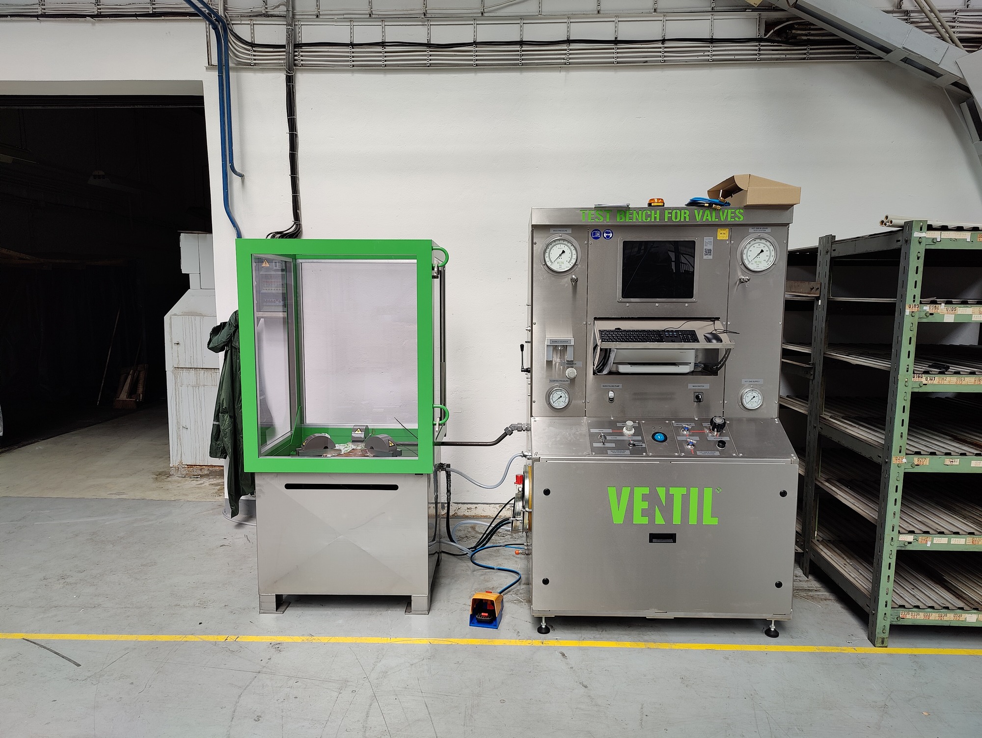
In-house VENTIL valve test bench.Archive photograph
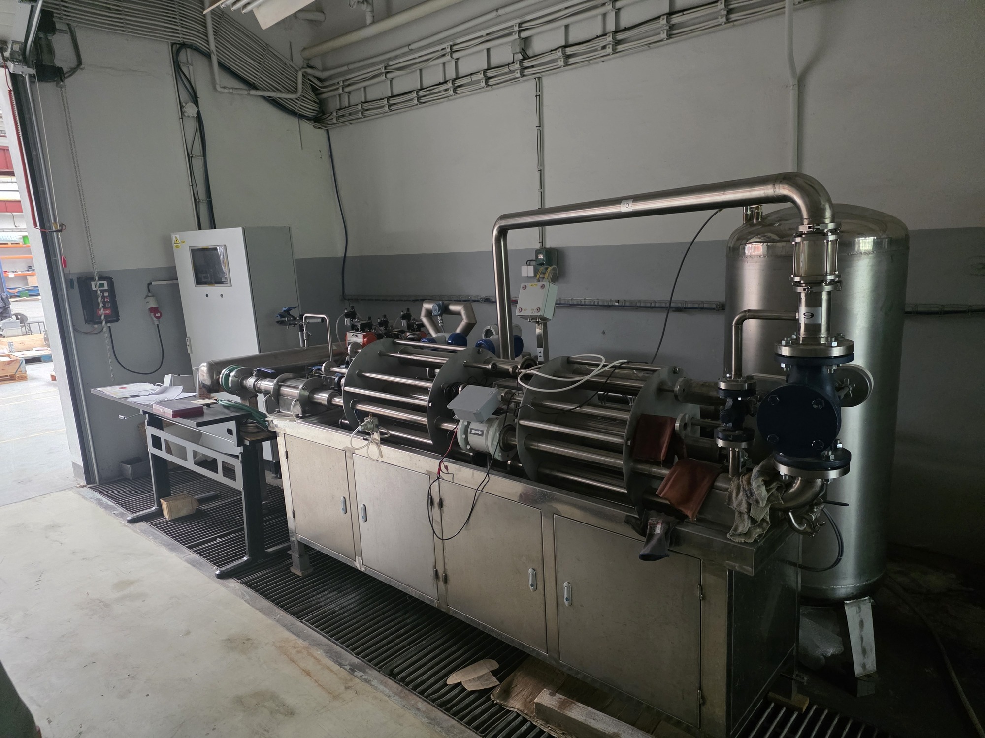
In-house flowmeter calibration and test line.Archive photograph
Manufacturing and delivery
Manufacturing equipment by operation.
The examples below describe the equipment used for particular operations. The actual machine, working envelope, handling capacity and responsible contractor are selected and confirmed against the drawings and project conditions.
Plate, profile, tube and bar stock prepared for structures, supports, guards, piping components and machined parts. Preparation takes account of subsequent welding, machining and surface requirements.
Equipment and tools
Laser cutting and guillotine shears for suitable sheet-metal parts
Band saws for profiles, tubes and bars
Clamping fixtures, stops and material guides
Deburring and edge-preparation tools
What determines selection
Technology is selected for the material, thickness, stock dimensions, required accuracy and batch size. Welded parts also require the specified joint preparation, clean edges and material identification after cutting.
Stage output
Identified blanks linked to the bill of materials, with prepared edges and the agreed dimensional checks.
02
Laser centre: cutting, marking, cleaning and welding
Our in-house laser centre supports cutting from manufacturing data, component marking, surface cleaning and welding. These operations are coordinated with design, production preparation and subsequent assembly.
Equipment and tools
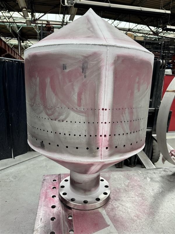
Laser cutting of contours, holes and perforations
Laser marking of components to approved artwork or text
Laser surface cleaning before subsequent operations
Laser welding of suitable parts and assemblies
What determines selection
The process follows material, thickness, geometry, access and the required result. Marking requires defined content, position and legibility; cleaning requires an agreed substrate condition, and welding requires joint preparation and an inspection method.
Stage output
Components with the agreed dimensions, marking, surface or weld, and records of specified inspections.
03
Turning, milling and deep-hole drilling
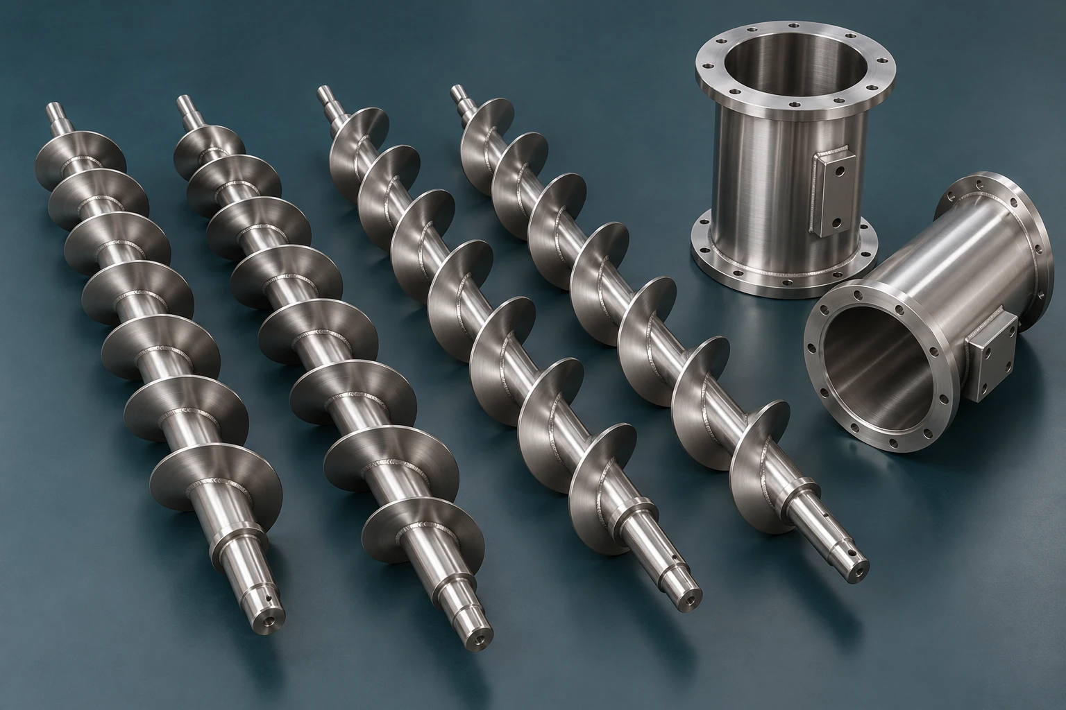
We manufacture flanges, bushes, adapters, threaded connections, bodies and other parts to drawings. Our gun-drilling equipment produces the deep sensor bores used in thermowell manufacture. Functional dimensions, mating surfaces and interfaces with the measuring assembly guide fabrication and inspection.
Equipment and tools
General-purpose lathes for rotational parts
A CNC milling centre and toolroom milling machines
Radial and pillar drills; drilling, reaming and threading tools
In-house gun drilling / deep-hole drilling for thermowell manufacture
Workholding fixtures, gauges and surface-inspection instruments
What determines selection
The route follows geometry, material, tolerances, surface finish and batch size. Thermowells also require a defined bore diameter and depth, wall thickness, insertion length and sensor fit. Dimensional capability and the inspection procedure are confirmed against the specific drawing.
Stage output
Machined parts and thermowells to approved drawings, material identification and records of the agreed dimensional and surface checks.
04
Welding and welded fabrication
Carbon-steel and stainless-steel structures, frames, piping parts and process assemblies. Joint design, operation sequence and fixturing address distortion and access for the required examination.
Equipment and tools
TIG and MIG/MAG welding equipment selected for the material and joint
Laser welding in our in-house laser centre
Welding tables, positioners and assembly fixtures
Shielding-gas and root-purge equipment where required
Weld gauges and equipment for the specified in-process checks
What determines selection
The process, parent and filler materials, WPS coverage, welder qualifications, welding coordination and inspection plan are defined together. WPQR requirements and NDT coverage follow the product, applicable rules and contract.
Stage output
A fabricated assembly with component identification, agreed weld traceability, dimensional checks and records of the required examinations.
05
Assembly, alignment and handling
Assembly of process units, installation of valves and instruments, piping work and modifications to existing operations. Preparation covers access, interfaces with surrounding equipment and the installation sequence.
Equipment and tools
Assembly fixtures, supports and alignment tools
Lifting and rigging equipment suited to the load and site access
Manual and powered installation tools
Torque tools and measuring equipment for specified joints and alignment
PRÜFTECHNIK OPTALIGN Smart EX for laser shaft measurement and alignment
What determines selection
Selection considers assembly mass and centre of gravity, the handling route, support capacity, access, tolerances and operating conditions. Equipment and personnel competencies are matched to the specific installation.
Stage output
An aligned and connected assembly, checked installation interfaces and the inputs needed for functional verification and as-built records.
06
Surface preparation: abrasive and wet blasting
Before coating and during refurbishment, we prepare surfaces by abrasive blasting and wet abrasive blasting. Suitable processes remove contamination, corrosion products and existing layers according to component condition and the requirements of the subsequent finish. Mechanical, laser or electrochemical cleaning complements preparation as appropriate to the material.
Equipment and tools
Abrasive blasting of components and assemblies
Wet abrasive blasting for surface preparation
Mechanical cleaning and surface-finishing tools
Pickling and passivation equipment for suitable stainless-steel components
Electrochemical cleaning equipment where appropriate to the product
Coating-thickness gauges and instruments for checking application conditions
What determines selection
Process, abrasive and operating conditions follow material, geometry, substrate condition and the required cleanliness and surface profile. After wet processing, residue removal, drying and the sequence of subsequent operations prepare the surface for paint or powder application.
Stage output
The agreed surface finish, visual acceptance and any specified treatment or coating-thickness records.
07
In-house wet painting and powder coating
Our in-house wet-painting and powder-coating facilities connect manufacturing with surface preparation and finishing. We provide surface protection for parts, weldments and structures according to the operating environment, appearance and assembly requirements. The paint or powder system is selected for the specific product.
Equipment and tools
Wet-painting facility for liquid coating application
Powder-coating facility for powder finish application
Masking of functional surfaces, threads and connections
Coating-thickness gauges and visual finish inspection
What determines selection
The brief defines material, component dimensions and mass, corrosion environment, colour, texture and coating thickness. The selected system determines preparation, masking, application and curing conditions. The result is checked against agreed acceptance criteria.
Stage output
Finished components with visual inspection and agreed coating-thickness records, ready for assembly or dispatch.
08
Dimensional and material inspection
Verification of critical dimensions, identification, surface condition and material specification before the next operation or handover. Measurement methods address the characteristics that determine function and acceptance.
Equipment and tools
Calipers, micrometers, dial indicators and suitable dimensional gauges
Roughness and coating-thickness instruments as specified
XRF analysers for suitable PMI applications
Calibrated instruments and references matched to the measured property
What determines selection
Selection follows the tolerance, range and required measurement uncertainty. For PMI, method suitability is assessed for the alloy and elements of interest, and results are linked to the component and material record.
Stage output
Inspection records identifying the checked component, acceptance criteria and instruments within the agreed scope.
09
Flow, pressure and temperature calibration
Our flowmeter calibration line, hydraulic pressure calibrator and temperature calibrator support instrument inspection and calibration. We check instrument response at agreed points and verify its output. Pressure, leakage and functional testing of valves and process assemblies complements instrument calibration as specified.
Equipment and tools
Our own flowmeter calibration line
A hydraulic pressure calibrator for pressure-instrument checks and calibration
A temperature calibrator for temperature-sensor checks and calibration
Valve and pressure-assembly test benches
Electrical calibrators, multimeters, power supplies and communicators for signal verification
What determines selection
The measured property, working range, medium, connections, calibration points and required records are confirmed for the instrument. The test procedure adds acceptance criteria and any customer attendance. Where accredited calibration is required, the appropriate scope is agreed with a suitable laboratory.
Stage output
A report identifying the tested item, conditions and results, with a calibration certificate or FAT and commissioning records where specified.
From the drawing to the site
Capacity is more than a machine name.
Part and material
Blank size, grade, tolerances, batch size and required surface determine the manufacturing route. Fixtures and inspections must be included in the preparation.
People and procedures
Equipment is matched with operators, qualified specialists and applicable procedures. Welding, NDT, electrical work and lifting activities have different competence requirements.
Handling and timing
Transport dimensions, lifting points, floor capacity, access and installation sequence can determine feasibility. These conditions are reviewed before the delivery date is confirmed.
Our flowmeter calibration line and DN 15 and DN 40 electromagnetic reference instruments support flow-instrument checks and calibration. Flow range, required uncertainty, connections and medium suitability are established for the instrument and configuration.
Our hydraulic pressure calibrator supports pressure measurement tasks. The brief defines test points, permitted fluid, connections and the required output. Checks assess instrument response and, where specified, repeatability and hysteresis.
Hydraulic pressure calibrator
Pressure gauge and transmitter checks according to configuration
A temperature calibrator complements our facilities for checking and calibrating temperature measurement applications. The method follows the sensor or transmitter type, range and connection. The brief distinguishes individual instrument checks, signal simulation and verification of the complete measurement loop.
Temperature calibrator
Temperature instrument checks according to type and connection
Facilities include a Keithley DMM6500 bench multimeter and equipment for checking displacer level instruments. Input simulation, output checks and tests in a process installation are distinguished when defining the task.
Keithley DMM6500
Displacer level instrument checks
VENTIL VC25SRV valve test bench
The bench combines gas and liquid systems with laser bubble counting for safety valve set-pressure and seat-tightness tests. The documented clamping range is DN 15–250; pressure, medium and fixtures are confirmed for each valve. A digital test report is supplied within the agreed scope.
Our laser shaft-alignment system supports installation and service of pumps, electric motors, gearboxes and other rotating equipment. It measures angular and parallel misalignment and determines the corrections needed to align the machinery.
Laser alignment of horizontal and vertical machines
Send your drawings, operating parameters or a short description of the change you need. We will review the technical interfaces and propose the next steps towards a quotation, clarifying any missing information with you.