PROJECTEnquire ↗
← All technologies

Connecting process equipment

Piping systems and installation interfaces

Piping is more than a list of tubes and valves. It must carry the medium under defined conditions, accommodate system movement and provide maintenance access.

The whole application matters.

A new route or modification combines the process diagram, spatial layout and specification of each line. Installation planning must include connections to the operating plant, component transport and access to work areas during the shutdown.

PIPING AS AN INSTALLED ASSEMBLYCONNECTIONVALVESUPPORTDRAINMaterials · expansion · access · joint inspection
Piping route, valves, supports and installation interfaces. Functional schematic; the actual configuration is project-specific.

From operating need to design.

01

Routes and connection points

A survey verifies positions, elevations, connections and surrounding obstructions. Engineering addresses supports, thermal expansion and loads at equipment connections. Forcing components into alignment cannot replace correct geometry.
02

Materials and joining

Medium, pressure, temperature and environment determine requirements for pipes, joints and gaskets. Welding and inspection must suit the material and applicable equipment regime. The description stainless steel alone is insufficient to establish suitability.

03

Shutdown and handover

Prefabrication can reduce site work when input dimensions are reliable. Work boundaries, inspection points, change records and conditions for return to service must be agreed before installation begins.

04

Active corrosion protection

Buried metallic pipelines and tanks can include cathodic protection and related service. The brief considers coating condition, electrical continuity and external influences. We define test locations, measurements and interfaces with the existing protection system.

05

Expansion joints and pipe movement

Metal bellows, lens-type and rubber expansion joints are specified for movement direction and magnitude, cycle count and service conditions. Design includes anchors, guides and allowable connection loads. An expansion joint is not selected by its face-to-face length alone.

06

Internal inspection before repair

Borescope inspection can reveal selected internal pipe or equipment surfaces without complete dismantling. Entry points, required views, cleanliness and location referencing are defined before inspection.

A scope you can specify.

Inputs that matter.

  • Medium, operating and design conditions.
  • Diagram, dimensions and connection points.
  • Material and corrosion requirements.
  • Space, supports and installation access.
  • Shutdown window and acceptance requirements.
  • Route, coating and existing corrosion-protection documentation; available measurement results.
  • Required axial, lateral and angular movements, cycle counts and pipe-support details.
  • Access openings, internal diameters, lengths and obstructions affecting inspection.
  • Inspection methods, evaluation criteria and links between findings and repair decisions.
Prepare your brief →

Outputs and acceptance.

  • Route documents and material list.
  • Installation and inspection plan.
  • Inspection records and as-built documents.
  • Defined test locations, agreed measurement records and proposed follow-up measures.
  • Expansion-joint data sheet with connections, movements and installation conditions.
  • Images referenced to inspected locations, with access limitations recorded.
  • Findings register and recommended follow-up inspection scope.

The actual scope and acceptance criteria depend on the application and contract.

Selecting a valve by its required function

First define control, isolation or reverse-flow prevention, then evaluate the valve, actuator and all operating conditions together.

On a small screen, scroll the table sideways to compare the selection criteria.

Selecting a valve by its required function
Principle or optionTypical applicationWhat to verify when selecting
Globe control valveContinuous flow, pressure or temperature control through an adjustable flow area.Kv/Cv at operating points, characteristic, cavitation or flashing, noise, shut-off leakage and actuator thrust.[1][2]
Ball valveQuarter-turn pipeline isolation; throttling requires a design intended for control duty.Bore and pressure loss, seats and seals, torque, cycling frequency and required position on loss of power.[3][2]
Butterfly valveCompact isolation or control where face-to-face length and weight are important.Design and seat type, permitted differential pressure, disc clearance, shut-off leakage and torque throughout travel.[3][2]
Check valveAutomatic reverse-flow prevention, for example on a pump discharge.Opening conditions, flow range, orientation, pressure loss and response to rapid flow changes.[4]
Sources for this comparison
  1. SAMSON – Control valve sizing ↗
  2. Emerson – Control Valve Handbook ↗
  3. Spirax Sarco – Isolation valves: rotary movement ↗
  4. Spirax Sarco – Check valves ↗

Reviewed on 18 October 2026. Selection is confirmed for the specific operating conditions and equipment design.

Pipe and tank materials: an initial comparison

Assess the complete fluid composition including impurities, concentration, temperature and loading; a material family designation alone does not establish product suitability.

On a small screen, scroll the table sideways to compare the selection criteria.

Pipe and tank materials: an initial comparison
Principle or optionTypical applicationWhat to verify when selecting
Carbon steelPiping and welded vessels where mechanical design and corrosion assessment support its use.Specific grade, toughness at design temperature, weldability, and corrosion protection or allowance.[1]
Austenitic stainless steel, e.g. 304LProcess piping and tanks requiring cleanability and resistance in an assessed environment.Chlorides and other impurities, cleaning chemicals, surface finish, crevices and weld-area condition.[3][2]
Austenitic stainless steel, e.g. 316LAn option considered for greater corrosion demands than standard chromium-nickel grades.The corrosion mechanism, temperature, concentration and cleaning regime; this grade is not universally chloride-resistant.[3][2]
Duplex stainless steelEquipment where corrosion resistance and mechanical strength are considered together.Specific duplex grade, service environment, welding procedure and thermal effects; properties vary across the family.[2]
Polypropylene, PP-HChemical piping and water treatment where the fluid and service conditions are suitable.Chemical resistance, allowable pressure versus temperature and service duration, expansion, supports and jointing method.[4]
Polyvinylidene fluoride, PVDFSelected chemical and clean-process piping with specific system material requirements.Resistance to the actual mixture, pressure and temperature, process cleanliness requirements, and joint and seal compatibility.[4]
Sources for this comparison
  1. SSAB – Pressure vessel steels ↗
  2. Outokumpu – Duplex grades and comparison with austenitic grades ↗
  3. Outokumpu – Corrosion tables and limits of their application ↗
  4. GF Piping Systems – Technical handbook for PP and PVDF pressure piping ↗

Reviewed on 18 October 2026. Selection is confirmed for the specific operating conditions and equipment design.

From the project portfolio.

All projects ↗
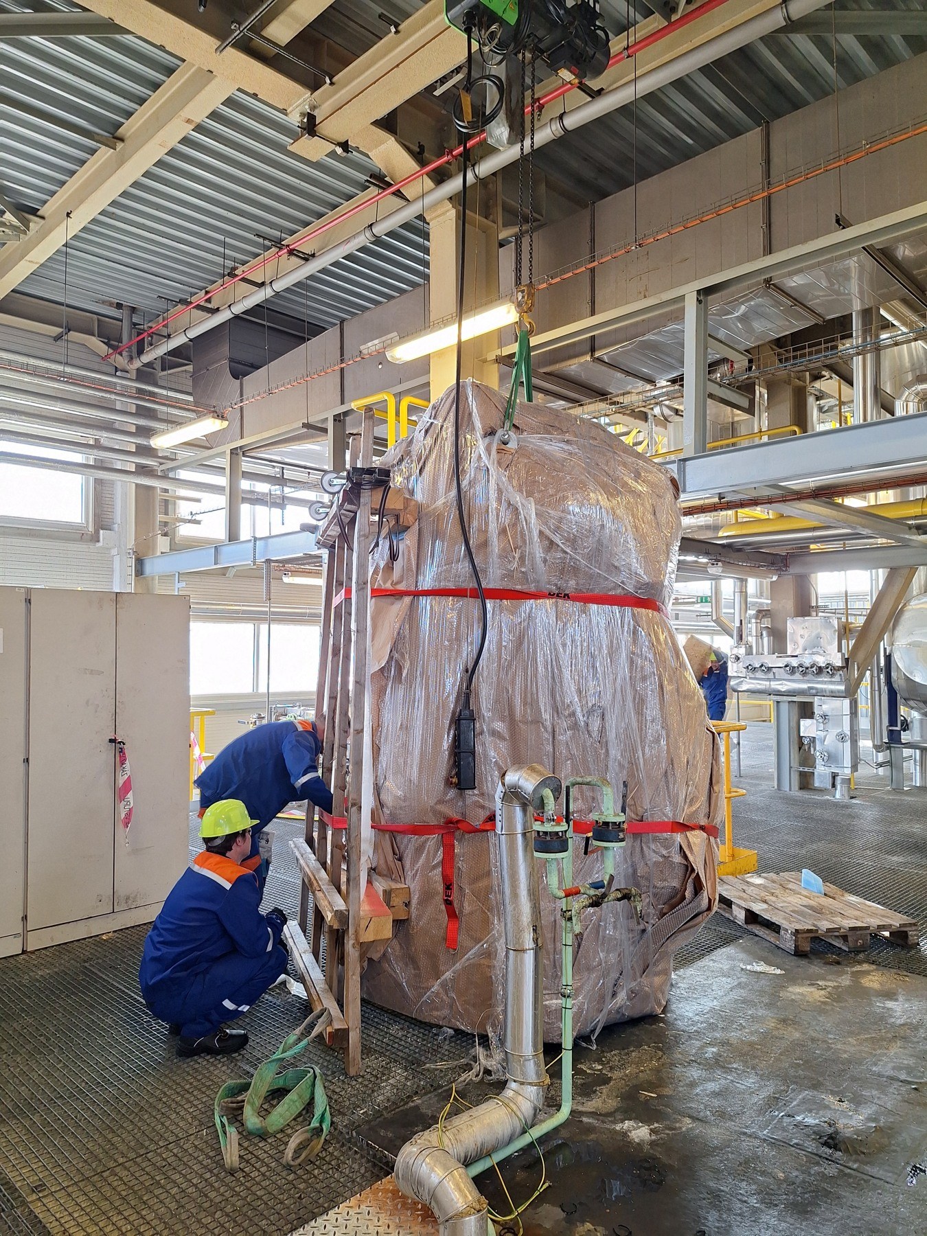
Project photograph.

Project 667 · Process plant upgrades

Acidification reactor replacement

Installation location: Lovosice, Czechia · 2024

Replacement of a 3.9 m³ reactor on a +6 m platform, including agitator assembly and modification of 15 pipe runs.

Broader project portfolioEquipment replacement, installation and connection

1 reactor with a volume of 3.9 m³Details →
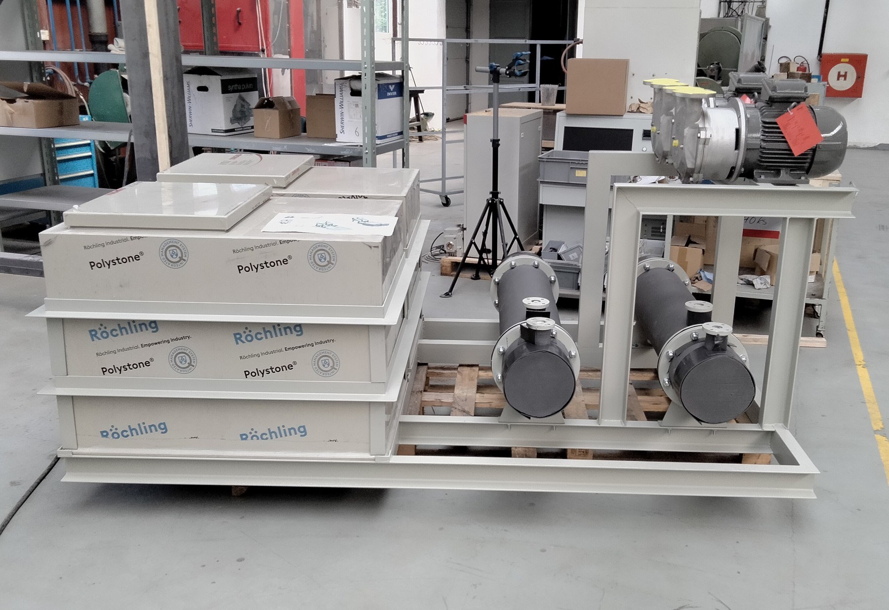
Project photograph.

Project 674 · Process plant upgrades

Vacuum system replacement

Location: Rybitví, Czechia · 2024

New vacuum assembly with PP tanks, heat exchangers, piping, instrumentation and controls.

Broader project portfolioProcess equipment refurbishment and installation

2 independent vacuum trainsDetails →
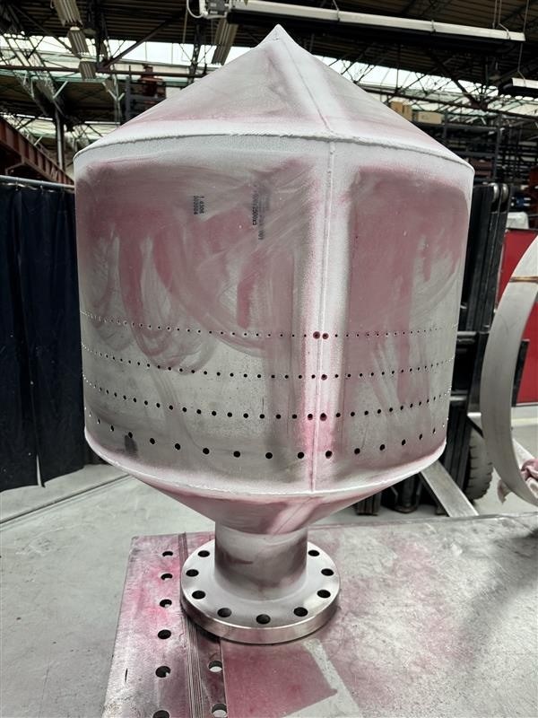
Project photograph.

Project 751 · Custom manufacturing

Ammonia distributor with crosspiece

Project location: Šaľa, Slovakia · 2024

One grade 1.4306 stainless steel ammonia distributor, with a net shipping mass of 270 kg and documented weld examinations.

Broader project portfolioCustom manufacture and supply

1 complete distributorDetails →

Expertise for this application.

Connect the whole solution.

Questions that shape the project.

Can components be made from old drawings?

After checking that they reflect the installation. Current survey data are especially important at tie-ins and in restricted areas where unexpected changes are difficult to accommodate.

Is the pressure test always the same?

No. The system, applicable regime and approved procedure determine inspection type, scope and conditions. A website description does not replace the test plan.

Can an expansion joint correct a misaligned connection?

Only within the allowance explicitly included in its design. Permanent installation offset can reduce available working movement and service life and must be assessed with the support arrangement.

A clear brief.
A practical next step.

Send your drawings, operating parameters or a short description of the change you need. We will review the technical interfaces and propose the next steps towards a quotation, clarifying any missing information with you.

Discuss your requirements ↗Prepare a technical brief →+420 731 771 147info@emkoproject.cz