The project in context
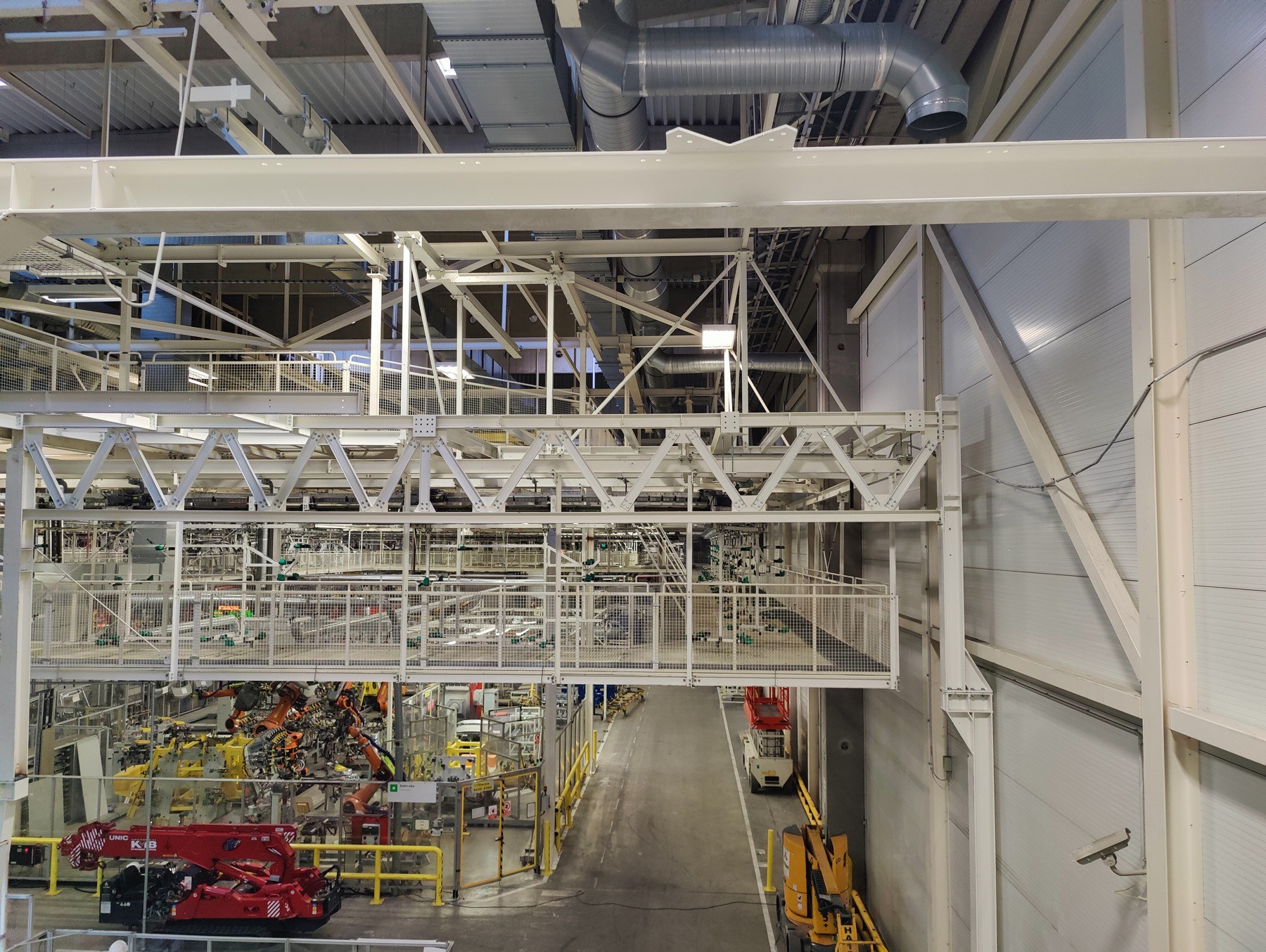
Technology in its operating context.
The project addressed automated supply of an assembly line with batteries held in handling frames. It combined stacked storage, three-axis handling, delivery of loaded frames to production and the return of empty carriers. The scope included engineering milestones, a prototype, mechanical supplies and integration work interfacing with the existing conveyor system.
Scope of work
- Mechanical design, prototype, 3D model, electrical design and safety concept
- Two three-axis handling units, jaw grippers and a two-level conveyor route
- Design of frame and battery identification, production sequencing and data interfaces
- Manipulator FAT, elevation-interface measurements and integration tests
Execution
The work combined mechanical and conveyor engineering, electrical design, controls and machinery safety. It progressed through prototyping, engineering handovers, manipulator testing and subsequent on-site integration.
Stacking, handling and conveyor interfaces
The mechanical arrangement uses two gantry manipulators to move frames along three axes. Each carries a gripper with two moving jaws. The layout has six loading locations and two rows of storage positions, providing a total of 12 mechanical positions for stacks.
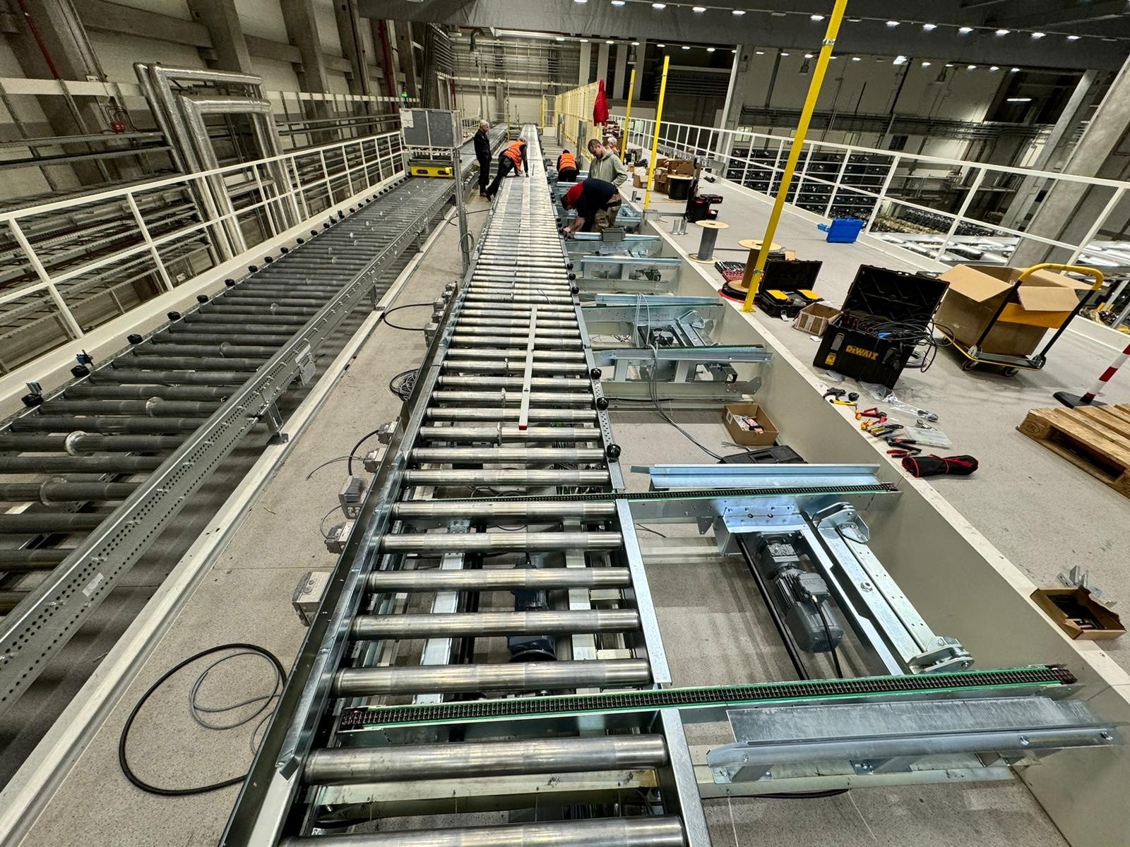
The upper chain-conveyor level carries battery-loaded frames towards the assembly line, while the lower level returns empty frames. A cross-transfer table with a lift connects the system to the existing conveyors. The layout also includes three unloading positions and dedicated positions for non-standard handling.
- The technical documentation specifies a maximum battery mass of 600 kg.
- Handling frames measure 1,970 × 1,500 × 310 mm or 2,100 × 1,500 × 310 mm; the base pallet is 240 mm high.
- The design includes loading guides, stops, fencing, service access and interfaces between the support structure and the floor.
Material identification and sequence control
The control design links frame and battery identification to assembly-line requests. The functional description covers occupancy tracking, first-in, first-out retrieval and selection of an approved alternative battery type according to the production call-off. It also addresses empty-frame routing and procedures for unreadable codes or non-standard handling.
Operation is divided into three areas with HMI panels: conveyors and the transfer point, the loading area with the main manipulator, and the unloading area with the second manipulator. Interfaces to adjacent equipment are specified through PN/PN couplers between separate Profinet networks.
- QR identification of handling frames and batteries, with tracking through transfer points.
- Siemens Simotion and Simatic control platforms, with visualisation for system status and operation of individual areas.
- The safety design includes fencing, light curtains, laser scanners and emergency-stop interfaces.
Handed-over stages and technical verification
The handed-over engineering milestones progressed from the frame and safety concepts through a loading-station prototype and a 3D model to electrical design, information architecture and mechanical manufacturing documentation. These were followed by the approved technical specification and the manipulator factory acceptance test in June 2024.
Integration work continued at the installation site in 2025. It included laser measurements of elevation interfaces and tests of stack loading, identification, retrieval and sequence control. Selected scenarios verified FIFO order and retrieval of an alternative battery type; these individual tests relate to specific system functions.
- January 2024: acceptance of the concept, safety design, prototype and 3D model.
- March–April 2024: handover of electrical design, information architecture and mechanical manufacturing design.
- June 2024: technical specification and manipulator FAT.
- March–April 2025: measurements of geometric interfaces and integration tests on the installed equipment.
Outcome
Engineering and partial delivery stages were handed over, followed by measurements and tests of selected functions on the installed equipment. The stated scope and financial band relate to those stages and do not establish final operational acceptance of the complete system.