The project in context
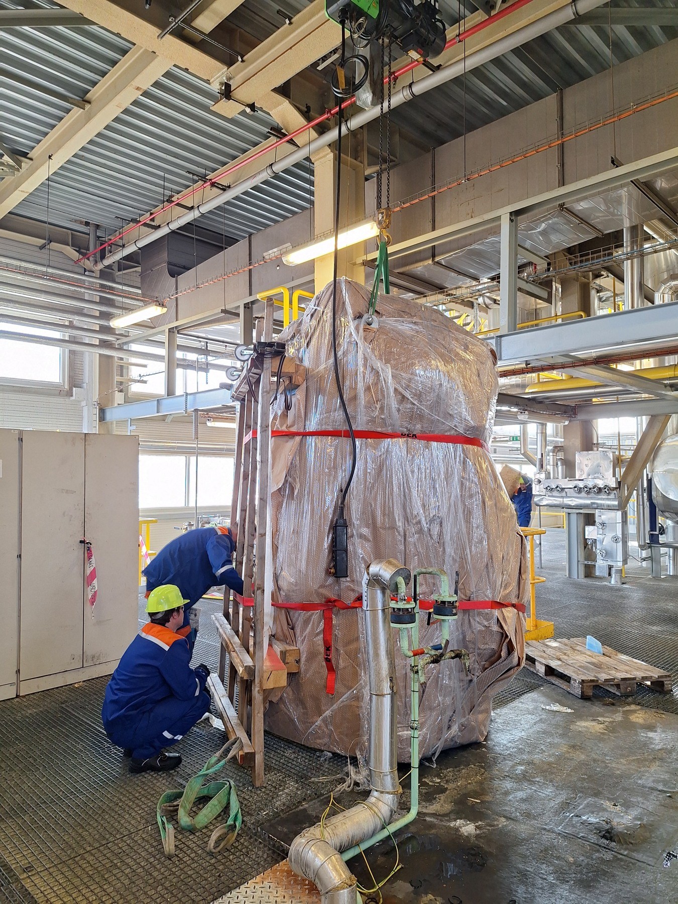
Technology in its operating context.
Replacement of the existing equipment required a split vessel design and interfaces to the original process pipework.
Scope of work
- Manufacturing design of the split tank, top cover and agitator support
- Stainless-steel parts in grade 1.4571 / AISI 316Ti
- Workshop fabrication and trial assembly, transport and on-site completion
- Weld map and plan for visual and liquid penetrant inspections
Execution
Workshop fabrication and trial assembly were followed by transport of the two sections, site welding, fitting of accessories and pipework connections.
A split structure for on-site assembly
The tank was designed as upper and lower assemblies, which were welded together at the installation site after transport. Manufacturing preparation covered the vessel geometry, top cover, agitator support and interfaces between the components. Workshop trial assembly took place before dispatch.
The drawings specify grade 1.4571 stainless steel, also designated AISI 316Ti, for the shell, bottom and main connection parts. The top cover and agitator support are separate steel components within the assembly. Splitting the tank allowed fabrication and completion work to be adapted to the installation conditions.
- A vessel internal diameter of 1,950 mm, as shown on the assembly drawing.
- The drawing specifies a 6 mm shell and an 8 mm bottom.
- Two main shell sections, a separate top cover and an agitator support.
Five nozzles for process connections
The connection layout serves pump suction, drainage, overflow and the incoming process stream. The fifth nozzle provides a spare connection. Engineering therefore addressed nozzle positions and orientation alongside placement of the new vessel in the existing process location.
The installation scope included dismantling the original tank and removing its lining, transporting the new assembly, completing welds, fitting accessories and connecting the pipework. The work combined stainless-steel fabrication with interfaces to the existing process equipment.
- 1 × DN 125 for pump suction.
- 2 × DN 100 for drainage and overflow.
- 2 × DN 150 for inlet and spare connection.
- The drawing specifies PN 16 flanges; this designation applies to the flange connections.
Weld map and inspection procedure
A weld map was prepared for the tank with 21 identified weld positions. It specifies full visual inspection and 20% liquid penetrant inspection for the individual positions, linking inspection requirements to specific locations on the assembly.
The inspection plan covered workshop welding and completion of the tank during installation. The invoiced scope included one tank with an agitator and its installation interfaces.
- A documented link between the construction drawing and the weld map.
- A combination of workshop preparation, site welds and inspection before completion of the work.
Outcome
A new stainless-steel tank with an agitator replacing the original equipment within the existing process area.